The facilities described here are the most primitive we could supply while still providing the minimum support required. They require that your program be able to access X-Windows. You may also develop your own tools and create your own displays using X-windows or some other display system.The concept is simple. You may display the values of a plane at every PE as an image on your workstation monitor. By looking at the display, you can notice patterns or abnormal values more efficiently than by looking at lists of numbers. When you find some point of interest in the displayed image, you can cause the values of interest at the point to be printed as numbers. You can overlay a display image with one or more BitPlanes. These operations may be performed using methods in your program or while interacting with a symbolic debugger(1).
To display an image, the Display method is applied to a plane. This causes an X-Window to be opened displaying the image of the plane. This window is labeled with text that you provide. For example,
    IntPlane x(256, 256);
    ...
    x.Display("Display of x");
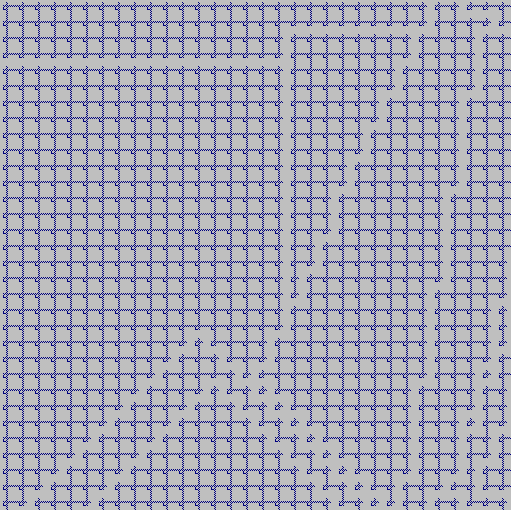
The plane is displayed as an eight level grey scale image.
The values in the plane are automatically scaled to the range 0 to 255 by using the minimum and maximum values from the plane.
The window created lasts as long as the plane that was used to create it. Therefore, do not display an expression as shown below because the display will not last long enough to be viewed.
(x + y).Display("Short Life Display");
Any changes made to the plane after it has been displayed will not be reflected in the display image.
In order to change the display image, you will have to apply the Update method(2).
You may remove a window sooner by applying the DisplayClose method to the plane that was used to create it.
The following code demonstrates these rules.
    {CharPlane x(ps);
     CharPlane y(ps2);
     ....
     x.Display("x"); // Display x
     y.Display("y"); // Display y in different window
     ....
     x = ...;  // Display of x & y not updated.
     y = ....;
     x.Update(); // Update x and not y
     y.DisplayClose(); // Close display of y
     ....
    } // Display of x closed automatically
You may also choose the size of the display window by specifying the number of rows and columns of the display.
When you do not specify a display size, the ICL will use the size of the plane.
Regardless of the size you specify, the minimum size will be 64 by 64 and the maximum size will be 512 by 512.
If the plane is larger than the display size, you will be able to use scroll bars to see all of the image.
If the plane is smaller than the display size, more pixels will be used to represent the value from one PE.
In any event, each PE will be represented by a square set of pixels to maintain the proper image projection.
x.Display("x in a 128 by 128 window", 128, 128);
    {Select active(...);
     ...
     x.Display("x with overlays");
     x.DisplayOv(x == 0, 1);  // Point out zero values as one color
     x.DisplayOv(active, 2);  // and the active PEs as another color
     ...
    }
Overlays remain until you change them or the display is closed. Note that the variable active is used to generate the overlay for the active PEs(4).
    ShortPlane x1(ps);
    ShortPlane y1(ps);
    FloatPlane magnitude(ps);
    BitPlane zero_crossing(ps);
    ....
    x1.Sample(" x1=%d");
    y1.Sample(" y1=%d");
    magnitude.Sample(" mag=%e");
    zero_crossing.Sample(" %d");
The sample specifications last as long as the plane exists.
To generate a sample print, you click the mouse at the desired PE on the display.
For example, the following message might be displayed for the above Sample specifications.
Sample(row,column) Active 0 mag=4.56 y1=23 x1=34
The sample message shows the row and column address of the selected PE and whether it is active or not, followed by your sample strings.
Your sample output is terminated by a newline.
Pause("Your message here is printed.");
ICLDisplaySamples(row_value, col_value);
You may also display the current Coterie configuration by applying the Display method to the pattern variable from a CoterieXXX declaration.
You may not specify a size for this display -- it is always 512 by 512.
    {CoterieWENS pattern(...);
        pattern.Display("Coterie Display");
        ...
    } // Coterie display closed.
0 - orange, 1 - red, 2 - green, 3 - blue, 4 - yellow