By definition, the individual processor elements PE in a SIMD computer all execute the same instruction at the same time. The ACU generates these instructions and sends them to each CAAPP PE simultaneously. Each PE has its own private memory (in CISM) that it uses to supply the data required by the instructions it is executing.
The PE are arranged in a two dimensional grid (1). We refer to the individual PEs by their row and column indexes as shown below.
PE((0,0))    PE((0,1))    PE((0,2))    PE((0,3))    PE((0,4))
PE((1,0))    PE((1,1))    PE((1,2))    PE((1,3))    PE((1,4))
PE((2,0))    PE((2,1))    PE((2,2))    PE((2,3))    PE((2,4))
PE((3,0))    PE((3,1))    PE((3,2))    PE((3,3))    PE((3,4))
PE((4,0))    PE((4,1))    PE((4,2))    PE((4,3))    PE((4,4))
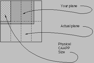
The Class Library for the IUA (2) is used to create programs to run on the Array Control Unit (ACU) and control the PE grid (CAAPP). The ICL allows you to consider the PE grid to be just about any size and maps your program to the actual size of the physical machine (3). Above we have a five by five grid. Most problems in image understanding require images of 128 by 128, 256 by 256, 480 by 512, and so on.
We map the images to the CAAPP grid so that each PE will access and operate on one pixel of the image. This allows us to process each pixel in an image in parallel.
The mapping is defined by a structure called a plane. A plane contains a two dimensional grid of data elements with an implied mapping of one data element to one PE (4). A plane has a size which is represented as a two element structure containing the number of rows and columns in the plane. A plane also has a type that describes the values that each data element in the plane may assume.
The ICL implements planes as its basic data type using the class facility of C++. This tutorial assumes you are familiar with C++, its syntax and its semantics. The ICL furnishes methods for operating on planes, maps the planes to the physical hardware, and generates the instructions that are sent to the CAAPP.
There are seven different types of planes -- each one with an analog to a standard C++ data type.
Type        Analog(5)        Min Value    Max Value    Bits
BitPlane    unsigned char         0            1          8
CharPlane   signed char        -128          127          8
UCharPlane  unsigned char         0          255          8
ShortPlane  short            -32768        32767         16
UShortPlane unsigned short        0        65535         16
IntPlane    int               -2^31       2^31-1         32
FloatPlane  float            -10^38        10^38         32
Because the PEs are bit serial devices, operations are actually performed using only the number of bits required to represent the range of values given above. Therefore, while you are generally able to ignore the types of integer scalars in C++, you must always be aware of the types of planes.
A plane variable is declared like other variables and follows the same lifetime and scoping rules as other C++ variables. When you declare a plane you must also specify the number of rows and columns that it will have.
    CharPlane image1(128,340);
    IntPlane      sums(200,300);
The variable image1 is declared to be a plane with 128 rows and 340 columns while the variable sums is declared to be a plane with
200 rows and 300 columns.
UShortPlane indexes(64,64)[5];
The variable indexes is declared to be an array of 5 planes with each plane having 64 rows and 64 columns.
In this example, each PE would hold one element from each of the five planes of indexes.
It is not possible to declare an initial value for a plane(6). Once a plane has been declared, it is not possible to change its size or type. The type and size information is used at compile time when possible.
    PlaneSize    ps(34,56);
    BitPlane    overflow(ps);
    PlaneSize    overflow_size(overflow);
In the above example, the BitPlane overflow is defined to have 34 rows and 56 columns.
overflow_size has the same size as ps.
In the remaining chapters, we will always specify a size when we define a plane and will use the variable ps when a size is needed but the exact size is not important.The size of a plane may be obtained using any of the methods shown below.
    unsigned short rows     = sums.RowSize();
    unsigned short cols     = sums.ColSize ();
    PlaneSize imagesize(sums.Size());
A PlaneSize variable, such as imagesize shown above, may be used to define another plane.
The row and column values of a PlaneSize variable may be obtained using the methods RowSize and ColSize.
Important Note
When you declare a plane and specify its size, the ICL may actually create the plane with a larger size than the declared size! The ICL always creates a plane whose number of rows is always an integer multiple of the number of rows of PEs in the physical CAAPP and whose number of columns is always an integer multiple of the number of columns of the physical CAAPP. Therefore, if the physical CAAPP is 64 by 128 and you declare a plane to be 70 by 140, the actual plane will be 128 by 256. In many cases you may ignore that this occurs. However, there are places where the difference between the size you declare and the actual size is noticeable:
Each element of the source is transferred in parallel to the destination. Each element is converted to the type of the destination using the same rules that are applied in scalar to scalar conversion.
    CharPlane x(ps);
    ShortPlane y(ps);
    x = y;
The scalar value is sent in parallel to every PE of the destination. The scalar is converted to the type of the destination using the same rules that are applied in scalar to scalar conversion.
    IntPlane z(ps);
    z = 123;
This is not allowed and will generate a compiler error.
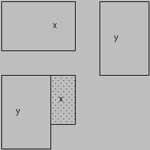
The ICL does not permit most operations, including assignment, to be applied to two planes with different actual sizes. They are not compatible. You can test for compatibility with the Compatible method. For example,
    void abc(CharPlane x, CharPlane y)
     {
      ...
      if (x.Compatible(y))
       {
        ...
       }
     }
The Compatible method returns a one if the two planes are compatible and zero otherwise.
Planes may be passed as arguments to functions just like scalar variables. When declaring the function argument types, do not specify the size of any plane(8). For example, the following function is written so that it may be used with any size of plane as its argument.
    IntPlane simple_ftn(CharPlane x)
     {
      PlaneSize ps(x);
      IntPlane result(ps);
      result = x * 2 + 1;
      return result;
     }
    PlaneSize       ps(x);
    UShortPlane     row_index(ps);
    UShortPlane     col_index(ps);
    IntPlane        index(ps);

    row_index    = x.RowIndex();
    col_index    = x.ColIndex();
    index        = x.Index();
The Index method returns a plane that is the actual size of the plane to which it is applied.
Each element for any PE is the row index of the PE times 2^16 added to the column index of the PE.
    UCharPlane x(64,64);
    ...
    x.Read(" my_plane" );
    x.Write(" my_plane_copy" );
The format of the plane file is determined by your organization.
You should contact your support personal if you need to know any of the details of this format.
Your installation may also supply library routines for transferring images to and from special IO devices.